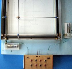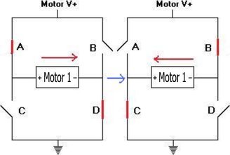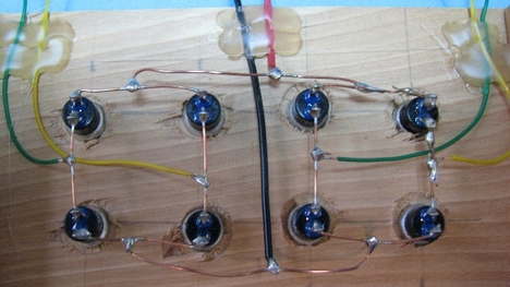
Although this post has a plotter working like an Etch A Sketch™ it is more about changing motor direction with a mechanical H- bridge. It is a simple way to demonstrate how the “real” integrated circuit works.
Small DC motors can be found in many toys, computers, printers, and RC systems, and the surplus market has every conceivable type of motor with varying voltage, torque, and RPM. One of the well known aspects of a DC motor is that it is easy to reverse the direction by simply reversing the plus and minus connections from the battery or DC source. But, literally changing the polarity manually seems a bit difficult to do quickly. So, an integrated circuit called an H-bridge is used to complete the task electronically. But, like many integrated circuit chips, it is not obvious how the task is accomplished. So, I decided to make a mechanical H-bridge with just momentary switches to illustrate how the chip works. And, rather than just spinning motors, I thought that making an Etch A Sketch™ looking device might be more interesting.
It is important to say that neither the mechanical dual H-bridge nor the X-Y plotter was ever meant to be finished projects. The H-bridge is for demonstration only, and the plotter is a test bed for project ideas that I can try and make. I have used DC motors, steppers, and servos to experiment with microcontrollers and the plotter was assembled with very little thought to any serious application. After all, it is built on foam board! Not a serious choice for a plotter! But, some of my projects are built for fun and entertainment as well as information. The link for ITP Physical Computing is here. I did make a mistake when describing the switches reversing the X direction. I should have said switches B and C. Apologies! So enjoy and comment.


 RSS Feed
